3-D Geometry in MFM
Details on the 3-D geometry conventions used by MFM.An important element of MFM is the convention used for describing 3-D geometry. This is particularly important to when placing devices, using antenna arrays, and working with channel objects.
MFM uses azimuth and elevation angles to describe 3-D angular information.
Azimuth—shown below as —is defined as the angle from the y-axis to the projection of the vector of interest onto the x-y plane. Azimuth angles range from to .
Elevation—shown below as —is defined as the angle from the x-y plane to the vector of interest. Elevation angles range from to .
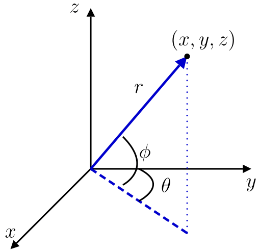
Explicitly, the 3-D geometry can be summarized as follows, where is the radial distance, is the azimuth angle, and is the elevation angle.
A vector of length in the azimuth-elevation direction can be converted to Cartesian components as
A vector having Cartesian components can be described as having length in the azimuth-elevation direction via
Uniform linear arrays are created along the x-axis by default, meaning that an azimuth of 0 degrees is directly in from the array (broadside).

Uniform planar arrays are created in the x-z plane by default, meaning that an azimuth of 0 degrees and elevation of 0 degrees is broadside.
